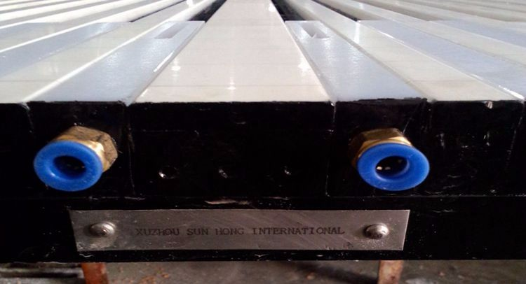
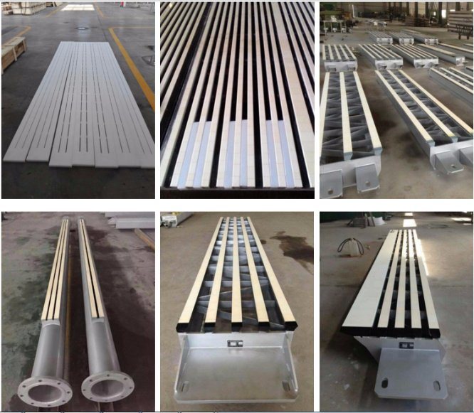
Foil Elements were introduced during the 1960s and took over as the standard dewatering elements at machine speeds where table rolls could no longer be used.A foil elements consists of a stationary blade fitted below the wire ,the upper side of which forms a small expansion angle with the wire ,generating an under pressure.However ,by choosing a small enough angle ,sometimes below one degree,a suitable suction pressure can be generated even at high wire speed.The accurate angle plays a great role during the dewatering process.
In 2018 we exported 10000 sets of foils to German client which obtains very good feedback.

Dewatering Elements:

Dewatering elements feature & structure :
| Â Â Alumina Ceramics Sub 99%Â AL2O3 | ||
| Property | Â Â Â Â Â Â Unit | Value |
| Bulk Density | Â Â Â Â Â g/cm3 | 3.86 |
| Hardness (HV) | Â Â Â Â Â Gpa | >14.7 |
| Bending  strength  |      MPa | ≥360 |
| Fracture toughness | Â Â Â Â Â Â MPa | 5-6 Mpa.m 1/2 |
| Coefficient of thermal expansion | Â | 7.0-7.5x10-6.0c |
| Porosity | Â Â Â Â Â Â % | <0.04% |
| Water absorption | Â Â Â Â Â Â % | <0.025% |
| Surface roughness |       --- | ≤0.5μm |
| Particle size | Â | Submicron |

| Vacuum Suction Box  & Forming Machine | Dewatering Box | Forming Board Box |
| UItra-fine grain /Uniform and dese | UItra-fine grain /Uniform and dese | Best choice of dot |
| Low friction coefficient | Low friction coefficient | Improve paper quality |
| Stable struture-tray-frame | Angles are avaible to choose | One time made ceramic |
| High-strength matrix of fiber glass /carbon fiber | Low adhesive rate for mixtures | Stable struture |
| Choices for the percentage opening | Effectively protect forming wire | High-strength matrix of fiber glass /carbon fiber |
| Lubricant equipment | Firmly fixed structure | Firmly fixed structure |
| Movable bar | Easy to replace | Easy to replace |
| Long service life | Long service life | Long service life |
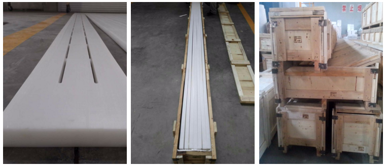
Packing & Delivery

Contact:
Jenny
www.sunhongco.comÂ
Cell:+86 15050826262Â Product Description:
Foil Elements were introduced during the 1960s and took over as the standard dewatering elements at machine speeds where table rolls could no longer be used.A foil elements consists of a stationary blade fitted below the wire ,the upper side of which forms a small expansion angle with the wire ,generating an under pressure.However ,by choosing a small enough angle ,sometimes below one degree,a suitable suction pressure can be generated even at high wire speed.The accurate angle plays a great role during the dewatering process.
In 2018 we exported 10000 sets of foils to German client which obtains very good feedback.

Dewatering Elements:

Dewatering elements feature & structure :
| Â Â Alumina Ceramics Sub 99%Â AL2O3 | ||
| Property | Â Â Â Â Â Â Unit | Value |
| Bulk Density | Â Â Â Â Â g/cm3 | 3.86 |
| Hardness (HV) | Â Â Â Â Â Gpa | >14.7 |
| Bending  strength  |      MPa | ≥360 |
| Fracture toughness | Â Â Â Â Â Â MPa | 5-6 Mpa.m 1/2 |
| Coefficient of thermal expansion | Â | 7.0-7.5x10-6.0c |
| Porosity | Â Â Â Â Â Â % | <0.04% |
| Water absorption | Â Â Â Â Â Â % | <0.025% |
| Surface roughness |       --- | ≤0.5μm |
| Particle size | Â | Submicron |

| Vacuum Suction Box  & Forming Machine | Dewatering Box | Forming Board Box |
| UItra-fine grain /Uniform and dese | UItra-fine grain /Uniform and dese | Best choice of dot |
| Low friction coefficient | Low friction coefficient | Improve paper quality |
| Stable struture-tray-frame | Angles are avaible to choose | One time made ceramic |
| High-strength matrix of fiber glass /carbon fiber | Low adhesive rate for mixtures | Stable struture |
| Choices for the percentage opening | Effectively protect forming wire | High-strength matrix of fiber glass /carbon fiber |
| Lubricant equipment | Firmly fixed structure | Firmly fixed structure |
| Movable bar | Easy to replace | Easy to replace |
| Long service life | Long service life | Long service life |
Packing & Delivery

Contact:
Jenny
www.sunhongco.comÂ
Cell:+86 15050826262Â
OUTER RETAINING CAP
This brass cap holds all the consumables onto the torch head.
It should only be replaced if there is visible damage such as slag build-up, dents or burns (on either opening), or if it is difficult to thread onto the torch head.
New Outer Retaining Cap
New
Worn Outer Retaining Cap
Requires Replacement
What`s wrong with this one? The top edge is dented and there is slag build-up on the lip. Both of which could cause the shield cap to not fit properly.
SHIELD CAP
Although the shield cap is not consumed by the plasma arc, due to its close proximity to the work piece it is susceptible to damage from torch crashes and pierces made too close to the plate.
As its name implies, the shield cap funnels the shielding gas for the purpose of additional nozzle cooling and improved cut edge squareness.
The orifice in the shield cap is crucial to edge cut quality, so it should be replaced when it becomes burnt, bent, or otherwise out of round.
An abrasive hand pad (not sand paper) can be used to remove splatter (slag) that has built-up on the shield cap.
Always inspect O-rings for possible damage such as nicks, cracks and tears. Make sure O-rings are properly lubricated using the manufacturer`s recommended lubrication. Refer to the manufacturer`s operator manual for lubrication specifications.
New Shield Cap
New
Worn Shield Cap
Requires Replacement
What`s wrong with this one? While the slag build-up could be removed with an abrasive pad, the orifice is out of round and cannot function effectively.
INNER RETAINING CAP
This piece has a copper body with a pressed-on insulator ring for seating into the shield cap.
The purpose of the inner retaining cap is to circulate coolant around the outside of the nozzle, and to distribute gas to the shield cap through tiny holes in the insulator ring.
This piece is not consumed by the plasma arc and can easily last up to 30 or more electrode replacements.
Replace only if the orifice is burnt, bent, out of round, or if the tiny holes in the copper body or insulator ring are plugged.
New Inner Retaining Cap
New
Worn Inner Retaining Cap
Requires Replacement
What`s wrong with this one? The orifice is out of round and the insulator ring is damaged.
NOZZLE
The copper nozzle channels the swirling plasma arc through a small orifice that varies in diameter depending on the amperage of the consumable. When new, this orifice will be perfectly round with a clearly defined sharp edge. This feature is the key to optimal cut quality.
Under normal cutting conditions, expect to use two nozzles for each electrode to maintain the highest cut quality.
The nozzle should be replaced when the orifice begins to wear out of round on either the outer or the inner bore. There may be some light swirl marks on the inside of the nozzle caused by arc starting, but this is not a cause for replacement.
Always inspect O-rings for possible damage, such as nicks, cracks and tears. Make sure O-rings are properly lubricated using the manufacturer`s recommended lubrication. Refer to the manufacturer`s operator manual for lubrication specifications.
New Copper Nozzle
New
Worn Copper Nozzle
Requires Replacement
What`s wrong with this one? The orifice is too out of round to function effectively and the sharp edge of the orifice has been eroded.
SWIRL RING
The swirl ring is machined from a high temperature resistant material such as Vespel® or ceramic, and is, therefore, not consumed by the plasma arc.
It serves as both an insulator between the electrode and nozzle, and a vessel to create the swirling action of the plasma gas needed to create precision cuts.
Care must be taken to ensure the small holes remain free of dirt and debris, and it should be replaced if any cracks or chips are detected.
Always inspect O-rings for possible damage such as nicks, cracks and tears. Make sure O-rings are properly lubricated using the manufacturer`s recommended lubrication. Refer to the manufacturer`s operator manual for lubrication specifications.
New Swirl Ring
New
Worn Swirl Ring
Requires Replacement
What`s wrong with this one? The small holes are plugged with debris.
ELECTRODE
The electrode can be made of copper or silver, or a combination of both, and contains a separate emitter rod insert, made of either hafnium or tungsten. The emitter rod offers less resistance to current flow than copper, which prevents the electrode from burning up while the high current arc is generated.
As long as the plasma arc is on, the emitter rod is being consumed. Eventually, it will reach a depth which will allow the arc to jump directly to the end of the electrode. This will result in an immediate blow out which will also destroy the nozzle and shield cap, and could also damage the torch head.
New Electrode
New
Worn Electrode
Requires Replacement
What`s wrong with this one? The wear depth (or pit depth) exceeds the allowable limit.
The safety zone for emitter wear depth is approximately 0.040" (1.02mm) for copper electrodes and 0.1" (2.54mm) for silver electrodes.
Always inspect O-rings for possible damage such as nicks, cracks and tears. Make sure O-rings are properly lubricated using the manufacturer`s recommended lubrication. Refer to the manufacturer`s operator manual for lubrication specifications.
Wearing Parts For Plasma Cutting
Wearing Parts For Plasma Cutting,Cutting Torch Wear Parts
Changzhou Edaweld Trading Company Limited , http://www.edaweld.com