Ultrasonic heat meter design
Ultrasonic heat meter working principle and system composition of thermoelectric power generation system
1. How does the ultrasonic heat meter work?
Ultrasonic heat meter is based on ultrasonic flowmeter to add temperature sensor to measure temperature, and calculate the heat supplied to users by measuring the flow rate of fluid and temperature difference between supply and return water. When the water passes through the heat exchange system, the flow rate measured by the flow sensor and the temperature of the water supply and the return water measured by the temperature sensor and the time when the water passes through the TDC-GP22 can be obtained by the calculation of the CPU. Or release heat. In practice, because the quality of the water through the heat exchange system is obtained by measuring the volume of water, the calculation method of the calorific value is mostly based on the European popular k-factor method. Its mathematical expression is shown in formula (1).
 (1)
(1)
In the formula, Q is the heat absorbed or released, J; V is the volume of the heat-carrying liquid, m3; Δθ is the temperature difference of the hot liquid returning water in the heat exchange circuit, °C; k is the thermal coefficient, it is the load The function of the hot liquid at the corresponding pressure, temperature and temperature difference.
2. System composition of thermoelectric power generation system
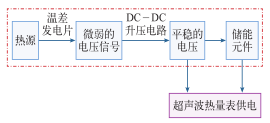
Thermoelectric power generation can also be called thermal power generation. It is through the Seebeck effect that the conversion between thermal energy and electrical energy is achieved. When there is a certain temperature difference between the water temperature in the pipeline and the room temperature, DC voltage can be generated at both ends of the temperature difference power generation sheet, and the reliability is high. When the temperature difference is 1° C., a voltage of about 70 mV can be generated. Thermoelectric power system functional block diagram shown in Figure 1. In this paper, a power generation chip of type TEC112706 is used. The heat source converts thermal energy into a weak voltage signal through a semiconductor power chip. Since the voltage of the voltage signal is low and the interference signal is also mixed, it cannot be directly used for the heat meter. The voltage signal is boosted by the DC-DC boost circuit, and the rectified output is relatively stable, and can be directly used by the ultrasonic heat meter. Since the ultrasonic heat meter uses a separate sleep mode, most of the time is in the LPM3 mode, that is, it is in a sleep state. At this time, the power consumption is very low. The power generated by the thermoelectric power generation system not only satisfies the use of the heat meter, but also superfluous. Electricity is stored in the energy storage element. When the MSP430F4371 MCU is in the AM mode, when the flow and temperature information is collected or verified, the high-speed clock is started to bring greater power consumption. When the converted power is insufficient, the stored energy component releases the stored power and supplements the heat meter. use.

Fig. 1 Functional block diagram of thermoelectric power generation system
Thermometer temperature difference power generation system hardware circuit
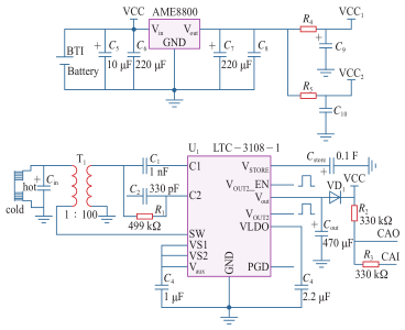
The power supply of the MSP430F4371 microcontroller and the timing chip TDC-GP22 in the ultrasonic heat meter mainly comes from two parts: a rechargeable lithium battery of 3.6V and 2200mAh, and a thermoelectric power generation system. The lithium battery and the thermoelectric power generation system together provide power for the heat meter. When the power generated by the temperature difference is sufficient, the surplus power can be stored in the rechargeable lithium battery while satisfying the power supply requirements of the heat meter; when the temperature difference is small, the battery is in the verification state for a long time, or the LCD liquid crystal screen is started, the temperature difference occurs. When power generation is insufficient, the lithium battery will be used as the main power source to compensate for the lack of temperature difference power generation. Heat meter power system circuit diagram shown in Figure 2.

Figure 2 Heat meter power system circuit diagram
In Figure 2, R4 and R5 act as current limiting resistors. Resistors R2 and R3 are connected to an internal comparator A to constitute a voltage detection module. Comparator A consists of an analog input, a comparator A core, a low-pass filter, a reference voltage section, and an interrupt. Through the software setting, the external analog input voltage is compared with the internal reference voltage to determine the state of the system voltage to monitor the system voltage. The low-frequency filter capacitor C7 is used to reduce the output ripple voltage, and the high-frequency filter capacitors C9 and C10 are used to improve the transient response of the load. BTIBattery is a 3.6V lithium battery that serves as the system's main power source. VCC1 and VCC2 convert the voltage of 3.6V to 3.3V through the regulator AME8800, which is used to power the TDC-GP22 chip and the MSP430F4371 microcontroller. When the thermoelectric power generation sheet has a certain temperature difference at both ends, a certain DC voltage signal will be generated at both ends. After this signal passes through the capacitor Cin to filter out the high-frequency signal, it enters the SW port of the LTC3108-1 through the primary winding of the boosting transformer and generates a self-excited oscillation signal through the N-channel inside the chip, thereby converting the DC signal into an AC signal for boosting. The boosted current flows through capacitor C1 into the LTC3108-1 internal rectifier and the charge pump begins to charge and then goes through the Vout port. When the Vaux terminal voltage is greater than 2.5V, the Vout port starts charging the capacitor Cout. When charging is complete, the device can be powered. When the power supply capacity is greater than its output capacity, the excess energy is stored by the capacitor Cstore. When the power supply capacity of the thermoelectric power generation chip disappears or becomes weak, the capacitor Cstore will directly supply power or voltage compensation to the system. The diode VD is added to prevent the lithium battery from reacting to the system when the thermoelectric power generation system voltage is lower than the battery voltage.
Experimental data measurement results
1. Measurement of power consumption parameters of ultrasonic heat meters
The ultrasonic heat meter designed in this article uses the MSP430F4371 microcontroller as the microprocessor, and the timing measurement chip selects the TDC-GP22 newly introduced by ACAM. The operating voltage of both is 3.3V. When the thermal watch is in sleep state, the average current consumption is about 5μA. When in the AM state, the average current consumption power consumption is about 10μA. The MCU operates intermittently. In the experiment, the ultrasonic heat meter collects the temperature once every 10 seconds, collects the flow once every 1s, and sleeps when it is not working. The specific measurement results are shown in Table 1.
Table 1 Ultrasonic heat meter power consumption under different conditions

Temperature difference power generation system in the pipeline when the water temperature is 70 °C, not only can meet the power of the heat meter, and when the signal sampling interval time of the test state and on-site working condition is designed as 1s, the service life of the built-in battery of the ultrasonic heat meter is still satisfied. (6 + 1) years of standard requirements, the use of thermoelectric power generation device in the case of the use of smaller capacity batteries, to meet the requirements of the corresponding indicators, to avoid the use of large-capacity battery waste of resources, the use of thermoelectric power to save energy, at the same time Protect the environment and have more promotion value.
2. Measurement of flow
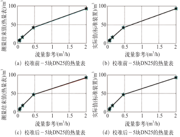
After completing the overall design of the thermoelectric ultrasonic heat meter, it can be operated stably for a long time after being debugged. According to the provisions of the heat meter industry standard document CJ128-2007, this article uses a heat meter with a pipe diameter of DN25. When the temperature is maintained at about 55°C, measurements are taken at five different flow points and the weighing method is used. The measured data of the heat meter verification device model RJZ15-25Z is shown in Figure 3.

Figure 3 Comparison of actual measurement results and standard data
3.5 DN25 heat meter corrected error.
According to the meter's rated flow Qn, set different flow points (flow rates) and different temperature conditions on the standard device to comprehensively examine the error of the meter being measured. Measured measurement results are calculated according to the following formula: E=[(indication-standard value)/standard value]×100%. The specific experimental data is shown in Table 2.
Table 2 Errors of 5 DN25 heat meters after calibration

The experimental results show that the temperature difference power generation system used satisfies the accuracy requirements under the laboratory conditions. Within the error range, the performance is reliable.
Vegetable processing methods There are methods such as canning, drying, pickling and quick freezing. The canning of vegetables is to put pretreated vegetables such as cleaning, peeling, cutting and blanching into sealed containers such as tinplate cans and glass bottles. A method of killing or inhibiting the growth of microorganisms in order to preserve vegetables for a longer period of time. Drying is a processing method that uses heat to dehydrate vegetables, that is, natural drying or artificial drying to increase the concentration of soluble substances in vegetables to a level that is difficult for microorganisms to use.
Vegetable processing methods There are methods such as canning, drying, pickling and quick freezing. The canning of vegetables is to put pretreated vegetables such as cleaning, peeling, cutting and blanching into sealed containers such as tinplate cans and glass bottles. A method of killing or inhibiting the growth of microorganisms in order to preserve vegetables for a longer period of time. Drying is a processing method that uses heat to dehydrate vegetables, that is, uses natural drying or artificial drying to increase the concentration of soluble substances in vegetables to a level that is difficult for microorganisms to use.
Vegetable Production Line,Vegetable washing machine,Vegetable sorting machine,Sterilizer,Vegetable filling machine
Jump Machinery (Shanghai) Limited , https://www.shanghaimachineres.com