First, the error caused by non-axisymmetrical flow
When the flow velocity of the fluid is axisymmetrically distributed in the tube, and in a uniform magnetic field, the magnitude of the electromotive force generated on the flowmeter electrode is independent of the flow velocity distribution of the fluid and is proportional to the average flow velocity of the fluid, rather than the axisymmetric flow velocity distribution. The magnitude of the induced electromotive force produced by the counter electrode is different for each fluid particle with respect to the geometrical position of the electrode. The closer to the electrode, the greater the induced electromotive force generated by the particle with higher velocity. Therefore, it must be ensured that the fluid velocity is axisymmetric. If the flow velocity in the tube is non-axisymmetric, it will cause errors. Therefore, in the optional electromagnetic flowmeter, it is necessary to ensure the straight pipe section as much as possible to reduce the error caused by it.
Second, the problem of fluid conductivity
The decrease of the fluid conductivity will increase the output impedance of the electrode, and the error caused by the load effect caused by the input impedance of the converter. Therefore, the lower limit of the conductivity of the fluid in the application of the electromagnetic flowmeter is stipulated as follows.
The output impedance of the electrode determines the size of the input impedance required by the converter, and the output impedance of the electrode can be considered to be dominated by the conductivity of the fluid and the size of the electrode.
Third, the effect of electrode lining attachments
When measuring fluids with attached deposits, the surface of the electrodes will be contaminated and often cause zero point changes, so care must be taken.
It is difficult to quantitatively analyze the relationship between the zero point change and the electrode contamination level. However, it can be said that the smaller the electrode diameter is, the less the influence is affected. In use, attention should be paid to the cleaning of the electrode to prevent adhesion.
When measuring a fluid with deposits, besides selecting a liner such as glass or polytetrafluoroethylene that is difficult to deposit, the flow rate should be increased. If the air bubble is uniformly contained in the fluid, the volumetric flow rate including the air bubble is measured, and the measured flow rate value is destabilized, introducing an error.
Fourth, the length of the signal transmission cable
The shorter the connection cable between the sensor (ie the electrode) and the converter, the better. However, some sites are limited by the location of the installation environment, and the distance between the converter and the sensor is relatively long. In this case, the maximum length of the connecting cable must be considered. The maximum length of the connecting cable between the sensor and the converter is determined by the distributed capacitance of the cable and the conductivity of the fluid being measured.
In actual use, when the conductivity of the fluid to be measured is within a certain range, the maximum length of the cable between the electrode and the converter is determined. When the cable length exceeds the maximum length, the loading effect caused by the cable's distributed capacitance becomes a problem. To prevent this from happening, use a two-core, two-layer shielded cable. A low-impedance voltage source is provided by the converter so that the inner shield and the core get the same voltage to form a shield even if there is a distributed capacitance between the core and the shield. However, if the core wire and the shield are at the same potential, no current flows between them, and there is no load effect of the cable, so the maximum length of the signal cable can be extended. In addition, a special signal transmission cable can be used to extend the maximum length between the transducer and the sensor.
V. Technical problems of excitation
Excitation technology is one of the key technologies for the measurement performance of electromagnetic flowmeters. Excitation methods can be divided into AC sine wave excitation, non-sinusoidal wave AC excitation and DC excitation in practical applications.
AC sine wave excitation, when the AC power supply voltage (sometimes the frequency) is unstable, the magnetic field strength will change, so the induced electromotive force generated between the electrodes also changes, so the signal corresponding to the calculated magnetic field strength must be taken out from the sensor as Standard signal. This excitation method can easily cause a zero point change and reduce its measurement accuracy.
Non-sinusoidal AC excitation is the use of square wave or triangular wave excitation below the industrial frequency. It can be considered as a way to generate a constant DC and periodically change the polarity. Because this excitation power supply is stable, it is not necessary to remove the magnetic field strength. Make changes. (end)
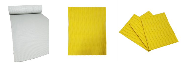
EVA Deck Pad for kiteboard deck pad and SUP deck pad comes in two ways normally. One is full sheet for DIY, the other one is die cutting based on customized design.
The full sheet deck pad can be in 230cm x 90cm or 90cm x 90cm size. Customers can cut the deck pad based on their board size, then simply peel and stick since the EVA deck grip we offered it with 3M adhesive. Besides, it can be also used in any other application for traction like boat flooring, yacht flooring and etc.

Eva Deck Pad,Surfboard Tail Pad,Kiteboard Deck Pad,Deck Grip Mat,Sup Board Deck Grip,Traction Deck Pad
Huizhou City Melors Plastic Products Co., Limited , https://www.evadecking.com