Research and Tentative Ideas on Exhaust Heat Recovery Technology of a 64-Dixel Diesel Drive Air Compressor SUN Donghui1,2, BAO Jinsong, ZHU Hui3 (1. School of Mechanical and Power Engineering, Shanghai Jiaotong University, Shanghai 200000, China; 2. Atlas Copco (Wuxi) Compressor Co., Ltd., Wuxi 214000, Jiangsu; 3. The national key of ISN in Xi'an University of Electronic Science and Technology is the relationship between fluid flow and temperature change, indicating that the two fluids are in the heat transfer process without phase change (boiling or condensation). The temperature t of the two flowing fluids varies along the heat transfer surface F. When flowing downstream, the temperature difference between the two fluids at the inlet is the largest, and gradually decreases along the heat transfer surface, the temperature difference to the outlet is the smallest, and 'always greater than tc2 In the case of countercurrent flow, the temperature difference of the two fluids along the heat transfer surface is more uniform, and th2 may be less than tc2. In the cold and heat flow heat exchanger, the water temperature of the pump tank is recovered linearly. y two 0.034).
+Exhaust water temperature + Inlet water temperature + Outlet temperature + Water temperature data analysis As shown, the water temperature of the water tank is also basically linear for the third experiment. According to the chart data analysis, the water temperature of the water tank also increases substantially linearly ( y=, A-0. + effluent temperature + inlet temperature + outlet temperature + tank temperature 2.2 Experimental data analysis The necessary data were analyzed by three experiments (see Table 1).
Table 1 Data Analysis Table Recycling Model Power / kw Exhaust Heat / J Converter Conversion Rate / % Heating to Boiling Time / s Increasing Temperature rc Water Volume / m3 Water Specific Heat Capacity - 1 Heat / J Heating Power / kW Exhaust Heat Power Factor 2.3 Experimental Inference Through the analysis in Table 1, a simple calculation formula can be obtained, that is, the time required to recover hot water using diesel-driven compressor waste heat is: At—the temperature difference before and after heating of the water tank, that is, the final temperature-normal temperature, ° c, P-diesel power, kW; the heat power coefficient of the exhaust gas, ie the product of the diesel exhaust gas dissipation power coefficient and the heat exchanger exchange rate, the specific value must be determined according to different heat exchangers of different models, in this experiment Take 50% of the data; Q a tank water volume, t. For field operations, the daily working hours can be basically determined, the power of the equipment used is fixed, and the formula can be reversed to calculate the conditions under which the work is performed every day: T hours The amount of hot water that can be heated.
For field workers, the amount of hot water available per day can be calculated based on the power status of the diesel engine.
After many times, the waste heat recovery test records of a variety of diesel air compressors can be seen that for a diesel-driven air compressor, there is nearly 50% of the power (if the heat exchange rate is considered, this coefficient will be larger) Dissipated in the exhaust emissions, this is a very amazing data.
For the author's company, the diesel fuel consumed by the test car is about 200m3 per year. More than 100m3 of diesel fuel is burned into heat energy, which is about 1000MWh. If you can effectively use these resources, the energy saving benefits are considerable. The direction of energy saving and emission reduction work.
3 Conclusion Through the above experiments, it can be concluded that the use of a diesel engine, if equipped with the corresponding heat exchange and supporting facilities, is equivalent to an additional input-free water heater with a diesel engine power of half. This has a good utilization value and application prospects in the era of energy shortage, and it has a good promotion effect on energy conservation.
-), male, Jiang Danyang, university, engineer, engaged in management of safety and environmental protection.
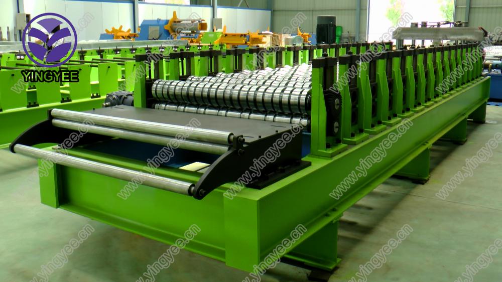
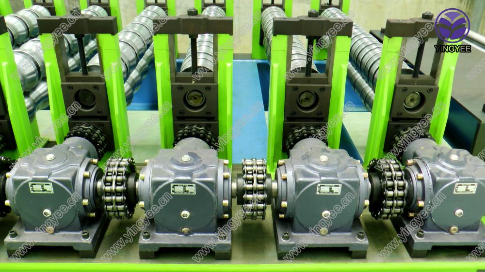
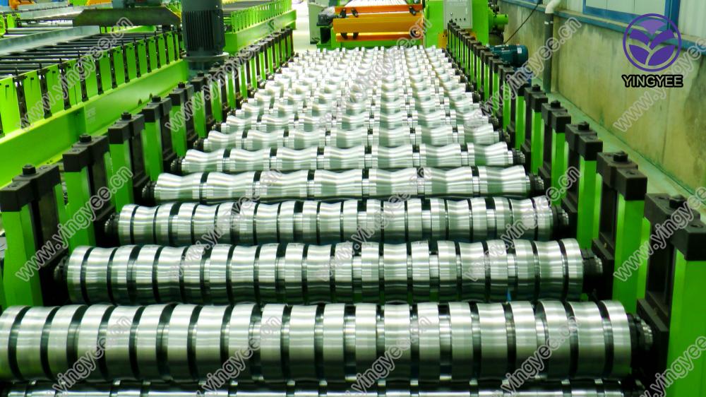
Glazed tile Roof Sheet Roll Forming Machine is not complicated, it can be used automatic production line equipment, also can be used partly mechanical devices and manual combination of production, but automatic production line equipment, automated processes, requires less labor, and it is PLC control, has advantages of fast speed.
Specifications:
Raw material
Colored steel, Galvanized steel, Aluminum steel
Material thickness range
0.2-0.8mm
Rollers
13 rows(according to drawings)
Material of roller
45# steel with chromed
Forming speed
15-20m/min(excluding press)
Shaft material and diameter
75mm, material is 40Cr
Type of forming machine
single station with chain transmission
Controlling system
PLC & Transducer(Mitsubishi )
Type of cutitng
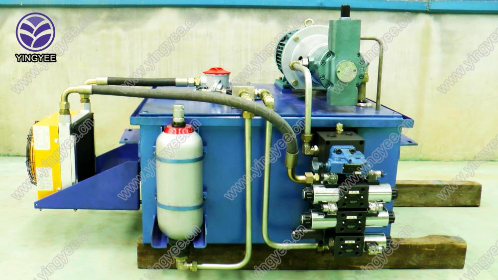
Hydraulic cutting
Material of cutting blade
Cr12 mould steel with quenched treatment
Voltage
415V/3Phase/50Hz(or at buyer's requirements)
Main motor power
7.5KW
Hydraulic station power
3KW
Working process:

Pictures:


Training and Installation :
1. We offer installation service local in paid, reasonable charge.
2. QT test is welcome and professional.
3. manual and using guide is optional if no visiting and no installation.
Certification and after service:
1. Match the technology standard, ISO producing certification
2. CE certification
3. 12 months warranty since the delivery. Board.
Our advantage:
1. Short delivery period.
2. Effective communication
3. Interface customized.
Glazed Tile Roof Sheet Forming Machine
Glazed Tile Roof Sheet Forming Machine,Cnc Glazed Tile Roof Sheet Machine,Aluminum Glazed Tile Roof Sheet Machine,Double Layer Glazed Roof Sheet Machine
YingYee Machinery and Technology Service Co.,Ltd , https://www.yingyee.cn