(a) Conjoined sprinklers

(b) Separating spray nozzles Figure 1 The small hole shot blasting flow-reflexing mechanism uses an indirect injection process because the pore size of the inner wall of the small hole shot is smaller (less than 10 mm) regardless of whether the spray head extends into the hole or out of the hole. The projectile jet stream cannot directly strike the inner surface of the projectile. Generally, the direction of the jet stream must be changed indirectly (Figure 1). The redirected projectile flow will form a scattering shape, and the different spray mechanisms will have different scattering shapes. This feature increases the difficulty of controlling the shot peening in the small hole. The required higher mixing ratio is compared with the direct shot blasting of the projectile. Due to the scattering of the projectile flow, the number of shots received by the sprayed area is relatively small at the same spray rate. It is required to increase the mixing ratio in the jet stream or jet stream. However, the proportion of the mixing pellets should not be too high. Otherwise, the pellets redirected by the reflector head will collide with each other due to the increase in density, thus lowering the efficiency. 3 Small-hole peening processing injection method The process control of small-hole peening processing is closely related to the injection method of the projectile. Different injection methods determine different process control schemes, and also determine the structure and control mode of the injection system. Therefore, the process characteristics of the small hole shot peening process determine that the injection method of the shot stream requires the use of an indirect jet method, which is implemented by a jet stream reflection mechanism, as shown in FIG. 1 . The key part of the reflection mechanism is the reflection head. There are usually two structures: one is the structure where the head is integrated with the reflection head (Figure 1a): the other is the structure where the head and the reflection head are separated (Figure 1b). Due to the larger structure of the conjoined showerhead, it is suitable for the shot peening of the inner wall with a large hole diameter. For the shot peening processing of the inner wall of the micro hole with an aperture of less than 10mm, a structure mode in which the head and the head is separated is preferred. This paper mainly focuses on the shot peening processing of the inner wall of the micro hole, and studies the structure mode, the spraying method and the control mode of the spraying process of the separation nozzle. For the separated structure, due to the different shapes of the reflection heads, the projectile flow is formed in different scattering shapes, and the process effect thereof is also not the same. It can be seen that the research on the design of the reflection head is the premise and basis for implementing the shot peening treatment process. To this end, the following types of reflective heads are proposed.

Fig. 2 Cone-type reflection head Cone-type reflection head Cone-type reflection head is shown in Fig. 2. Generally, the angle between the conical surface and the bottom circle should be 45°. After the projectile flow hits the conical reflector, it scatters the inner wall of the percussive hole in all directions and theoretically forms a disk. When the hole diameter of the workpiece is small, it is difficult to excrete pellets, especially when the reflector head moves against the flow of the pellets. Therefore, when the diameter of the workpiece is small, the angle between the conical surface and the bottom circle can be appropriately increased. In order to facilitate the expulsion of the projectile, the relationship between the gap between the outer wall of the reflector and the inner wall of the hole (∆x/2) and the diameter r of the projectile is ∆x = (3 6 6) r. The reflection surface of the circular-arc reflective head Concave arc shape, see Figure 3. When the projectile flows into the concave arc-shaped reflective surface, it scatters the inner wall of the percussive hole in all directions and theoretically forms a disk. However, experiments have shown that due to the effect of the concave arc surface, the projectiles that hit the wall of the hole are relatively concentrated, which greatly increases the efficiency of the projectile. According to the focusing principle of light, the center of the concave arc is selected on the inner wall of the hole when the reflection head is placed in the hole of the workpiece, as shown in FIG. 3 . According to the principle of plane geometry, the radius of the concave arc is R=[(1+∆x/2)2+(∆x/2)2]1â„2=(12+∆x+∆x2/2)1â„2

Figure 3 Circular reflector

Fig. 4 Reflective heads of oblique planes The first two types of reflectors on the inclined plane reflectors have the problem of projectile excretion to varying degrees. If the diameter of the hole to be machined is small, the shaft diameter of the reflector must be limited in order to smoothly excrete the projectile. If the shaft diameter of the reflecting head is too small, the working surface cannot reach the processing requirements of the reflecting surface, and the rigidity of the reflecting shaft will be affected. For this purpose, we propose a unidirectional beveled reflector as shown in Figure 4. The reflecting surface of this type of reflection head has an inclined surface at an angle of 45°, and the inclined surface of the projection head after the impact of the projectile stream is redirected to unidirectionally strike the wall of the hole. In addition to up and down movement, this type of reflector head also needs to rotate around its own axis, that is, spiral up and down. 4 Process control mode of small hole shot peening processing According to the basic principle of small hole shot peening processing control, process control is mainly to its main process parameters (such as air pressure, spray speed, mixed pill ratio, shot time, shot count, etc.) In order to control the movement of the injection system, we propose the idea of ​​implementing the process control using the "coupling motion of the shower head and the reflection head" to use the "spray head + reflection head → coupling motion" mode. The coupling methods include the following options. The control mode of “head and head is synchronous and reciprocating at the same speed and the jet flow intensity is constant†in order to ensure the consistency of the process effect in the strengthened region of the workpiece, the shot intensity of the projectile flow against the inner wall of the hole can not be changed too much, so the design requires the shot flow The injection distance from the spray head to the inner wall of the hole is not changed. Therefore, a process control mode of “constant jet flow rate, synchronous movement of the spray head and the reflective head†is used, as shown in Fig. 5a. The characteristic of this method is that the control of other process parameters is relatively simple and the process consistency of shot peening is good, but the synchronization mechanism of the spray head and the reflector head makes the structure and control of the injection system very complicated. Since the nozzles are to protrude into the processing holes, this process control mode is suitable for strengthening the inner walls of the holes with a relatively large aperture.


(a) Simultaneous and uniform motion of spray head and reflector

(b) The nozzle is fixed and the reflector head moves at a uniform speed

(c) The nozzle is fixed, the reflector head moves at a uniform speed, and the jet flow intensity changes. Fig. 5 The schematic diagram of the process control of the coupling motion of the nozzle head and the reflector head The control mode of “fixed nozzle, the reflector head moves back and forth uniformly and the jet flow intensity is constant†in order to simplify the mechanical structure And institutional control systems, mostly using fixed injection method, that is, "fixed nozzle, reflective head reciprocating motion, jet intensity constant" process control mode, see Figure 5b. Its characteristic is that the mechanical structure of the injection system is relatively simple and easy to control: The disadvantage is that the consistency of the reinforcement process is poor, ie when the reflector head is close to the nozzle, the intensity of the inner wall of the shot blast hole is large, and the reflector head is far away from the nozzle. The strength of the inner wall of the shot blast hole is small, which results in poor consistency of the whole wall reinforcement of the hole. Therefore, this kind of process control method is used for the strengthening treatment of the inner wall of the small hole with a shallow hole depth. The control mode of the “fixed nozzle head and reciprocating transmission movement of the reflector head and variation of the jet flow intensity†of this process control scheme (see Fig. 5c) is to constantly change the jetting intensity of the shot flow, that is, to control the jet flow intensity between the reflective head and the shower head. The distance varies and changes to overcome the disadvantages of poor process consistency in the second control mode described above. Its characteristic is that the mechanical structure and its motion control are relatively simple, but for different workpiece materials and different reflection head strokes, when the reflection head approaches or leaves the nozzle, the variation law of the projectile jet flow intensity is extremely difficult to grasp. Longer time will increase processing costs. This mode is suitable for mass production applications. The control mode of “fixed nozzle and reciprocating transmission movement of the head and constant jet flow†is a mode that combines the above mentioned second and third schemes, overcoming the disadvantages of the above three schemes and basically satisfying the reinforcement of the inner wall of the micro-deep hole. Process requirements for processing. It controls the movement speed of the reflecting head according to the change of the distance of the reflecting head approaching or leaving the nozzle. When the reflection head is close to the nozzle, due to the increase of the projectile jet flow intensity, the movement speed of the reflection head is required to be quickened, so that the time for the shot blasting is shorter: When the reflection head leaves the nozzle head, the intensity of the projectile jet stream is relatively small, so the requirement is The relatively slow movement of the reflection head causes a relatively long time for the projectile to strike, thereby achieving a balance of the striking strength as a whole. Compared with the speed control of the single reflection reciprocating motion and the “coordinated control of the reflection head movement speed and the jet flow intensityâ€, not only is the structure much simpler, but also it is easy to grasp the control laws of different strokes.
Roller Shutter Door and Door Frame Forming Machine
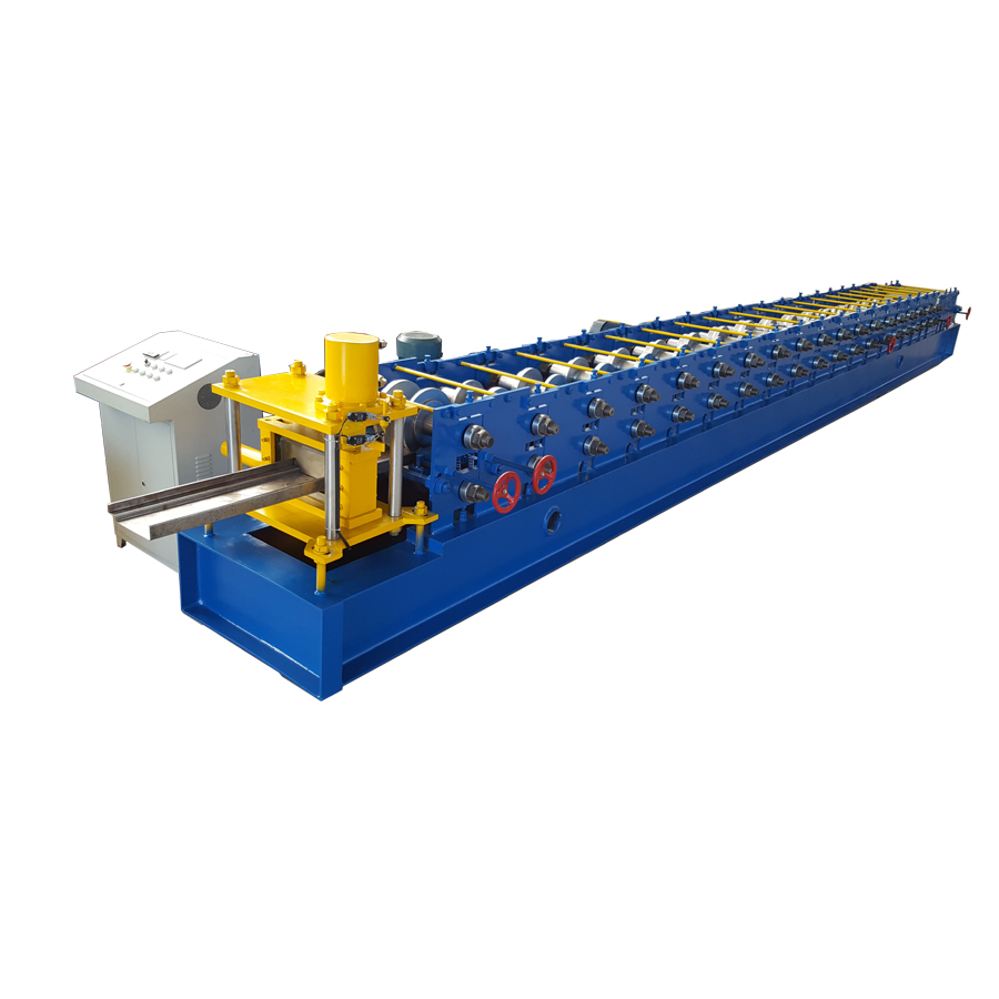
This door frame machine is designed according to cutstomer require. One machine can produce same profile but different sizes. It saves lots of cost, and get customers great satification.
The shutter door machine has many type of design. The austrilia type use wide raw material width, and easy to make the door. The small type of shutter door strip has nice appearance, and durable product. Besides, there are some other type of shutter door machine, like anti-wind shutter door machine and fire proof shutter door machine. The fire proof shutter door machine has the steel frame with EPS inside.Such as steel door frame making machine.


Roller Shutter Door and Door Frame Forming Machine Series
Roller Shutter Door Forming Machine,Door Frame Forming Machine,Door Frame Roll Forming Machine,Shutter Door Roll Forming Machine
Botou Xianfa Roll Forming Machine Factory , https://www.rollformingmachinecn.com