1 Ultrasonic wave detection method Automotive gears are generally electron beam or laser welded. Possible defects are mainly cracks, pores and insufficient weld depth. The depth of the weld is generally controlled within the range of 2 to 4 mm. Whether it is a disc gear or a shaft gear, their structure determines that ultrasound can only enter from the inner cylindrical surface. From the analysis of the propagation characteristics of the ultrasonic wave, since the size of the ultrasonic reflected wave is related to the area of ​​the reflector, the ultrasonic propagation direction is preferably perpendicular to the larger surface of the defect. Non-penetrating and crack-like planar defects are generally the most dangerous.
Ultrasonic waves incident perpendicularly to the inner cylindrical surface of the gear will also be incident perpendicularly to the planar defects. For the schematic diagram of ultrasonic propagation, see 1. In 1, the ultrasonic transducer placed in water emits pulsed ultrasonic waves, which are incident on the inner cylindrical surface of the gear through water. At the water/steel interface, most of the ultrasonic energy is reflected back to the transducer, forming the interface echo in Figure 1(b). Boost a small portion of the energy entering the inner ring of the gear. If the welding quality is good and there are no defects, the sound waves are incident on the outer wall of the gear casing through the weld zone, and most of them are reflected back, and a very small part leaks into the water. A small portion of the reflected portion returns to the ultrasonic transducer through the steel/water interface to form a B1 echo in 1(b). If there is a defect in the weld, there is still a part of the ultrasonic energy reflected from the defect, forming the defect echo F.1 in 1(b), the water/steel interface echo pulse B0 and the steel/water interface echo B1. The amplitude is much larger than the amplitude of the defect echo F, and the relationship is: Bo>>B1>>F.
The experimental results show that if the ultrasound is a plane beam and the defect is a flat bottom hole of 0.5, the amplitude of Bo may be several thousand times larger than that of F. Generally, the trailing edge of the ultrasonic pulse has a "tailing" that is difficult to eliminate. . The extent of "tailing" will gradually decrease over time. If the defect is closer to the water/steel interface, the defect will be masked by the trailing tail. The correlation between the defect pulse and the trailing pulse is excellent and difficult to distinguish. The general ultrasonic probe has a long tail and cannot meet the flaw detection requirements of small automobile gear welds. Therefore, high-resolution probes with higher frequencies must be used. One of the characteristics of high-frequency ultrasound is its light-like propagation characteristics, so it can be focused with a lens like light. Properly increasing the ultrasonic frequency, using focusing techniques, can focus the ultrasound to a specific depth, the depth at which the defect is located. At the focus, the reflection of the ultrasound can be considerably enhanced, and sharply weakened beyond the focus. In this way, the difference between the Bo amplitude and the F amplitude can be reduced. If the defect/interface distance is 3 to 5 mm, the gap may be reduced by an order of magnitude.
The diameter of the ultrasound probe must be appropriate. In Figure 2, under the weld is the interface between the gear collars. This small interface is a fake reflective surface for ultrasound. If a small portion of the detected ultrasonic beam is scattered to this interface, since its reflection ability is much stronger than that of the flat bottom hole of 0.5, a strong reflected wave is formed, causing false detection. Therefore, the ultrasonic beam should be limited to the depth of the weld. Too large may cause false reflection of the interface; if it is too small, the ultrasonic beam cannot cover the entire weld. Therefore, when the weld depth changes, it must be considered whether the original probe is suitable. If not suitable. The probe with the same weld depth must be redesigned.
Also. The ultrasonic probe must be positioned accurately. If the positioning is down, it may cause false reflection at the inner jacket interface. If it is on the upper side, it may cause false reflection caused by the upper surface of the weld. Therefore, when the weld depth is changed, the height adjustment of the probe and the rework comparison test block should also be changed.
2 Automatic detection system development For the needs of small and medium mode gear ring weld inspection, an automatic detection system was developed. According to the detection principle, function and technical requirements, the gear ring weld ultrasonic automatic detection system consists of five parts: ultrasonic detection subsystem, mechanical scanning subsystem, control subsystem, ultrasonic detection signal processing and display, system calibration test piece. The block diagram of the system is shown in Figure 3.
1) Ultrasonic detection subsystem. The detection subsystem for realizing the detection of the gear electron beam girth weld includes the following parts: an ultrasonic flaw detector, a detector, a single chip control card, an A/D data acquisition card, and a computer for processing and displaying the detection information. The ultrasonic flaw detector excites the detector to transmit and receive ultrasonic waves, and the A/D capture card converts the ultrasonic echo signals into digital signals for storage in a computer.
2) Mechanical scanning subsystem. The upper part of the mechanical scanning subsystem is embedded with a detection tank, which has a dual-station probe station. The interior can be divided into a probe station drive system and a cylinder-water injection cylinder for completing the water-splitting function. The function of this subsystem is mainly to ensure the correct positioning between the ultrasonic probe and the workpiece to be inspected, and to control the normal movement of the workpiece to be inspected.
3) Control subsystem. The control subsystem consists of industrial computer, single-chip control card, various relays and stepper motors. The control system adopts the distributed control, which consists of the upper computer and the lower computer. The lower computer sets and controls the parameters of the controlled object, and transmits the collected information and status to the upper computer through the communication interface, and receives the command of the upper computer at the same time; The machine performs comprehensive command, decentralized control and centralized management on the lower position machine.
4) Ultrasonic detection signal processing and display subsystem. It consists of signal processing, image processing and display software installed in the industrial control unit. It analyzes the collected data to obtain the detection information of the workpiece, makes a digital image of the information, and makes a judgment on whether the workpiece is qualified. It is a versatile software package for signal processing, identification and automatic interpretation.
5) System calibration test piece. The calibration test piece is a test piece that is identical to or close to the geometrical dimensions of the workpiece material and the joint surface to be fabricated.
The function of the calibration block is 2: (1) to determine the sensitivity of the flaw detection; (2) to determine the geometric positioning of the ultrasonic probe and the center of the weld. In order to ensure the reliability of the test results and diagnostic conclusions provided by the system, the system can only enter the detection state after this check and self-test to confirm its correctness.
3 Test Results Figure 4 shows the test results obtained by testing the actual weld gear ring weld using the developed test system. The uppermost curve in the figure is the reflected echo at the weld of each test point obtained by one round of the gear ring weld inspection. The place with large amplitude is the defective place. The middle curve is the interpretation curve obtained by dividing the upper reflection amplitude curve (the threshold is obtained by detecting the standard detection test block), and the larger than the threshold is 1-defective, and less than the threshold is 0-no defect. The lower part of the figure is a numerical statistic of the defects. The statistical parameters include the number of defects, the size and position of each defect, and the proportion of defects in the total weld perimeter. Finally, it is concluded that the total length of the defect in this system is less than the length of the weld seam 10 (or other specified value), and the “qualified†display is issued; if the weld length exceeds 10, but less than 40, the “defective†is issued. Display; when the temperature exceeds 40, the "Insufficient Depth of Welding" display is issued.
4 Ending this paper, the ultrasonic automatic detection technology of small and medium modulus welding gear ring welds was studied, and an automatic detection system was developed. The detection system can automatically perform ultrasonic inspection on small and medium modulus gear ring welds of various specifications and realize The automatic interpretation function. The test results (the percentage of the length of the defect and the length of the weld) are compared with the criterion and the curve and the statistical angle of attack α = 1°, and the side slip angle β = 0. The angular velocity of rotation is all zero. The mine trajectory is simulated by Matlab/Simulink.
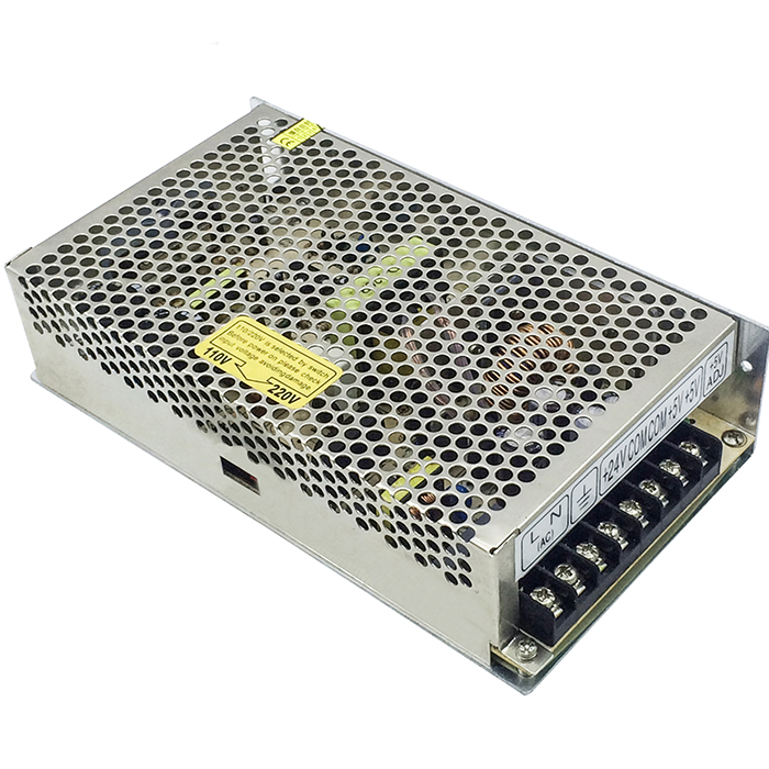
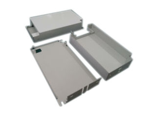
Metal stamping Power Adapter Metal Housing
The Timeplex group is one of the leading manufacturers of metal, plastic, electronics / industrial consumer products and home appliances products, R/C drones in China ,founded in 1989.
During these years ,Timpelex has established strong confidence and goodwill with our customers. This is our promise: We manufacture top quality products according to your design or ours, with competitive prices and prompt delivery.

We specialize in the below business for our customers around the world.
1. Metal Stamping Parts, Heatsink .
2. Plastic Injection parts.
3. Electronic Finished Goods Assembly.
4.R/C drone and smart toys.
5.OEM/ODM manufactory.
Main customers: Walmart ,UK Sky TV, Osram, BAGEletonics, Hasbro, Intermec, PPG, Fender, A.O.Smith ,Delta ,Vtouch, East West; Electrolux, Panasonic electrician etc.
Wish to have an opportunity to cooperate with you in the coming days .

More services we offer:
Besides of Metal Stamping Components,the Amplifiers metel chassises and Panels, we also complete solution for OEM/ODM Products & components, offer services of deep drawing services, EMI metal shielding parts, heat sink ,plastic molding products for custom, PVC Fittings ,pvc conduit fittings, Plastic Injection Components, Metal Stamping Parts, home appliances accessories ,R/C drone and smart electronic toys etc.
Power Adapter Metal Housing,Transformer Metal Box,High-Precision Stamping Proofing,Custom Sheet Metal Stamping
Timeplex Industrial Limited , https://www.catimeplexhk.com