1VH2-280 reducer use conditions and damage The VH2-280 reducer is a two-stage vertical parallel shaft spur gear reducer produced by a foreign company. It is used for the air-cooling fan system of a 600MW steam turbine generator set in a domestic power plant.
The fan is axial flow type, model G-TF91D6-G75.
The selected reducer model is VH2-280, the reducer adopts vertical installation, the input shaft is connected with the motor, the output shaft is connected with the fan, and the reducer is connected with the fan bridge through the foot hole.
The main technical parameters of the VH2-280 reducer are as follows:
Motor power P1=90kW speed n1=200/1000/1100r/min reducer transmission ratio i=1601 During the use of the reducer, gear pitting, broken teeth and other damage occur frequently during the warranty period, appearing in the second stage pinion Pitting corrosion and broken teeth are particularly serious, as shown in 1.
Due to the damage of the reducer, the air-cooling system of the steam turbine generator set cannot work normally, especially in the summer peak of power consumption, the frequency of damage is greater, which seriously affects the normal operation of the whole unit. Therefore, it is necessary to carry out technical transformation in time to solve the existing problems.
After testing, the gear material is 20Cr2Ni4, the tooth surface hardness is HRC57. The contact of the gear tooth surface is good, the gear is the carburizing and quenching grinding process, and the machining precision is high, which is equivalent to the national standard 6 precision.
2 Analysis and calculation of the cause of damage to the reducer 21 Reason analysis According to the analysis of the damage on the site, the reasons for the damage of the reducer are:
(1) In the design and selection, the extreme working conditions that may occur on the site are not considered enough; (2) When selecting the type, the selected gearbox has a small bearing capacity and specifications; (3) Two-stage gear strength distribution of the reducer The optimization is not achieved and the gear modulus selection is too small.
22 transmission form and gear parameters VH2-280 is a two-stage cylindrical gear reduction transmission, vertical installation, transmission structure diagram shown in Figure 2. 2 Transmission structure diagram The main parameters of the reducer are the first stage: A1=200, Z1=17, Z2=69, B1=90; the second stage: A2=280, Z1=18, Z2=71, B2=130.
23 Gear Strength Calculation Gear strength calculation is based on the calculation method of involute cylindrical gear bearing capacity GB/T3480, which is equivalent to ISO/DP6336 international gear strength calculation standard.
The calculation formula of the tooth surface contact fatigue strength safety factor is SH=HGHSHmin(1) where SH is the calculated safety factor of the contact strength; HG is the contact limit stress of the calculated gear, N/mm2; H is the contact stress of the gear, N/ Mm2; SHmin is the calculated safety factor of contact strength.
The calculation formula of the tooth root bending fatigue strength safety factor is [1] SF=FGFSFmin(2) where SF is the calculated safety factor of the bending strength; FG is the calculated bending ultimate stress of the gear, N/mm2; F is the root of the gear Stress, N/mm2; SFmin is the calculated safety factor for bending strength.
Calculate according to the above two formulas, SHmin, SFmin value see 1.
1 Minimum safety factor reference value [1] Minimum safety factor required SHmin, SFmin failure probability is less than 1/1000015 Failure probability is less than 1/1000125 Failure probability is less than 1/100100 Failure probability is less than 1/10085
24 original reducer gear calculation results The calculation results of the gear safety factor of the original reducer are shown in 2.
2 gear safety factor calculation result first level second level name code Z1Z2 name code Z1Z2 contact safety factor Sh104104 contact safety factor Sh084084 bending safety factor Sf195195 bending safety factor Sf11811858
From the calculation results, the contact and bending strength of the second stage can not meet the design specifications, which is consistent with the phenomenon that the second stage pinion pitting and broken teeth often occur on the spot.
3 Improvement measures For the above analysis and calculation, in order to meet the requirements of production and use, it is necessary to develop a new reducer that meets the requirements of working conditions and has reasonable parameters. The design is subject to considerable restrictions, considering that conditions such as on-site installation cannot be changed. First of all, in the structure to ensure that the original installation size is unchanged, arranged in a compact manner, increase the center distance of the gear, improve the load capacity of the reducer. Secondly, aiming at the gear bending capacity, the gear parameters are optimized, which greatly improves the bending strength of the gear and the reliability of the gear unit. Finally, the gear material is made of 18Cr2Ni4WA high-quality low-carbon alloy steel, which adopts deep carburizing and surface hardening grinding process. The gear processing precision is up to 5 grades, and the tooth surface is shot peening.
The main technical parameters of the newly designed reducer and the original reducer are shown in 3. The calculation results of the gear safety factor are shown in 4.
3 New and old reducer gear parameter comparison 4 New reducer gear safety factor calculation result The safety factor of the original reducer and the new reducer is shown in 5.
5 new and old reducer gear safety factor comparison original reducer new design name first level second level first level second level contact safety factor 104084136122 bending safety factor 195118301223186110298208
4 Summary Through the comparison of the calculation results, the newly designed reducer has a greatly improved bearing capacity. After nearly two years of on-site use, the product fully meets the requirements for use. The newly developed reducer makes the whole machine safe and reliable, reduces maintenance time, reduces operating costs, and completely replaces imported products. It has been used in batches and has significant economic benefits.
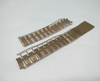
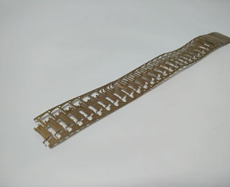
Metal stamping Precision Copper Stamping Parts
Looking for ideal Metal Stamping Components , complete solution for OEM/ODM Products and component Manufacturer & supplier ? We have a wide selection at great prices to help you get creative. All the Metal Stamped Housing are quality guaranteed. We are China Origin Factory of Metal Stamping Shell Factory. If you have any question, please feel free to contact us.
Precision Metal stamping parts descriptions :
 • Electronic connectors
• Sensor components
• Thrust washers
• Surface mount pins
• Transfer stampings
• Printer cartridge blades
• Medical components
• Insert moldings
• Fuse clips
• Furniture parts
• And more.
More services we offer:
Besides of Metal Stamping components, we also complete solution for OEM/ODM products & components, offer services of deep drawing services, EMI metal shielding parts, heat sink ,plastic molding products for custom, Plastic Injection Components, Metal Stamping Parts, home appliances accessories ,R/C drone and smart electronic toys etc.

Precision Copper Stamping Parts,Aluminum Stamping,Brass Stamping Parts,Metal Stamping Parts
Timeplex Industrial Limited , https://www.timeplexhks.com